Project Overview
This crane design project, completed for ENGI 2203, focuses on creating a
miniature-scale crane capable of lifting, transporting, and placing a rotor
within a wind turbine hub. Built with limited materials and under strict size
and weight constraints, the crane simulates real-world engineering considerations
in wind turbine installation and demonstrates proficiency in materials, dynamics,
and statics.
My Role & Key Contributions
- Conceptual Design & Analysis: Contributed to brainstorming crane
mechanisms (mobile vs. tower crane) and performed initial torque, moment, and
stability calculations.
- Report Compilation & Editing: Coordinated the writing of the
design documentation, ensuring requirements, constraints, and design logic
were clearly explained.
- CAD & Rapid Prototyping Liaison: Communicated with TAs for
3D-printed components (rack & pinion, rotor holder) and integrated them into
the design plan.
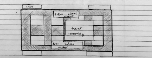
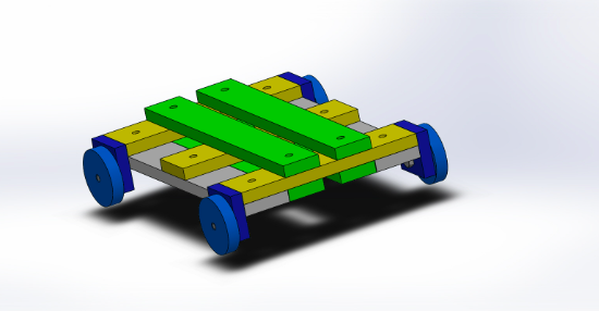
- Build & Assembly: Assisted with base assembly (wheel mechanism)
and tower assembly to ensure the crane fit within the 4x4 foot area.
Problem & Requirements
Summary of the Problem
Cranes are crucial for constructing wind turbines, lifting rotor assemblies
without damage. Our task was to build a scale model using a predefined kit
plus limited 3D-printed parts. The crane needed to pick a 223g rotor from
a 4x4 foot area (2.36" off ground) and place it precisely in a hub
at 18.9" height—without external interaction or dragging.
Constraints
- Only kit materials + 15 cubic inches of rapid prototyping material.
- Must fit in a 4x4 foot zone, accommodate rotor (17.52" blade) and hub (6.29" x 4.72").
- No external interaction after initial placement of rotor in crane grip.
- Crane must not tip over with or without the 2.18N rotor load.
Requirements
- Lift and place the rotor safely inside the hub.
- Operate without damaging the rotor or dragging it on the ground.
- Standalone operation (no external forces beyond initial setup).
- Must be competition-ready on specified dates.
Design Concept
Our final crane is a hybrid between a mobile crane (for movement on wheels)
and a tower crane (for vertical height). Key subsystems include:
- Base Movement Mechanism: A skid-steer approach using two front
wheels driven by independent motors for rotation and precise positioning.
- Rotor Pick-Up Mechanism: A rotating “finger joint” on the boom
arm that clamps onto the rotor, then pivots to correctly align it for hub insertion.
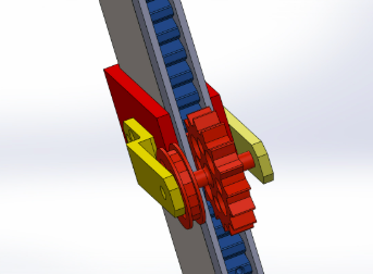
- Vertical Movement (Rack & Pinion): The crane arm ascends or descends
along a 3D-printed rack mounted on the tower, driven by a motor-powered pinion for
precise vertical placement.
Challenges & Outcomes
-
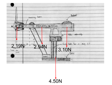
Stability vs. Mobility: Balancing a lightweight design with enough
counterweight to stay upright when lifting the rotor.
Outcome: Used a skid-steer base with well-placed support towers and
verified through moment calculations.
-
3D-Printed Parts Dependency: Delays in receiving critical printed
parts (rack, pinion, rotor bracket) stalled final testing.
Outcome: Created contingency plans for part breakage and tested partial
prototypes to ensure correct tolerances.
-
Rotor Orientation: Needed a reliable mechanism to rotate the rotor
from horizontal to vertical.
Outcome: Switched from a complex pulley-based system to a simpler
rotating finger joint, reducing build complexity and potential failure points.